|
| |
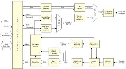
| The PIU 1355 Communication Link |
The PIU data-processing unit is responsible for the managment
of all the commands and data products which flow between the
Rosetta spacecraft and the five RPC experiements. Since the
experiments have very different processing capabilities and
data products, the PIU needs a common interface to each in
order to minimise the complexity of the PIU embedded software.
A protocol based on the exchanges of 8-byte packets has been
developed at Imperial College, using the IEEE 1355 standard
as a starting point. Most of the complex low-level functionality
of the IEEE 1355 is hard-wired into a programmable Gate-Array
device, so that the overhead on the host processor is minimised.
Each IC-LINK comprises two such transceiver devices, one in
the experiment and one in the PIU.
The IEEE 1355 specifies a number of methods for point-to-point
communication. Each method is divided into a physical layer
(options for electrical or fibre-optic connection), and a
logical layer (protocols for data exchange, incorporating
various levels of data security). For RPC, the major design
requirements are minimise the mass and power of the transceivers,
whilst providing the host processor with a simple and reliable
interface. Since the logical and physical layers are separate,
it is possible to use a logical layer normally intended for
use over optical fibre, where data and data-clock are encoded
together. This reduces the interconnect between transceivers
to a single line in each direction -- one for transmit and
one for receive. An optical fibre connection is not appropriate
in this application, but can be replaced by a cable since
the data rates are modest.
When serial data is to be transmitted over a single line,
i.e. without the use of separate clock and strobe lines, the
chosen coding must allow for recovery of the clock from the
data. One such coding, known as 'three of six', is described
in the IEEE 1355 standard. Each byte is represented as two
six-bit symbols, where each symbol has three ones and three
zeros (hence the name). There are twenty such valid symbols,
sixteen of which are used for data and two for control symbols.
The two control symbols are used in combination to build control
characters; these are used during initialisation and also
to maintain flow control. This coding provides a set of rules
which enables the boundries between characters to be identified,
and the synchronisation to be subsequently held and checked.
In the IC-LINK some of thr spare symbols are used to define
an additional control character which represents a timing
signal. This is used to send a common time reference pulse
to all the experiments simultaneously. The clock signal is
multiplexed on the link with the data in a manner which is
totally transparent to the data.
For the Rosetta mission, the low power and low mass properties
of the IC-LINK are particulararly important. Mass is reduced
compared to a more traditional serial interface, since the
data, the data clock and the timing signals are all carried
on a single line. The power consumed by the transceiver is
minimised by clocking the device as slowly as possible. A
balance must be struck between power and the desired rate
of the link. The interface to the host microprocessor is designed
to be both simple and flexible. The experiments and the PIU
exchange packets of a fixed length, with the flow control
and error checking handled entirely within the hardware of
the transceiver device. The simplicity of the interface is
necassary since the RPC experiments operate a variety of microprocessors
and, in the case of the MAG experiment, with no processor.
Whilst the IC-LINK is optimised for use in a microprocessor
based system, the MAG experiment is able to operate the IC-LINK
through provision of status pins on the transceiver device.
The link status may be polled by reading a status register,
or the descrete status pins on the device may be used to generate
interrupts.
As stated previously, the IC-LINK comprises two transceiver
devices connected together to from a point-to-point link.
In the RPC package, the PIU and the electronics for the LAP,
MIP and MAG experiments are located within a single electronics
box enclosure. In this configuration, the transceivers are
connected together by just two wires, one for data in each
direction. This is the single-ended mode, suited to units
which share a common ground reference, and minimises the mass
and power consumed. For interfacing to the IES and ICA experiments,
which are remote units some metres away from the PIU electronics,
a balanced differential interface is used. This requires two
wires -- data and the complement of data -- in each direction.
The power consumed by the differential interface is higher,
but this arrangement improves signal quality at the remote
unit.
Used in the RPC package, the IC-LINK provides a simple means
of interfacing between the experiments and the PIU, and is
efficient in its use of the scarce mass and power resources.
Handling the flow-control and error checking functions within
the transceiver device itself, the IC-LINK allows the experiments'
processors to concentrate on their scientific tasks.
This page was last updated September 2002.
|